Can’t find your discipline or profession? Write to us and we’ll
do our best to work something out.
Every project is unique.
We adjust our services to your needs.
The Libera BLM is a processor for signals coming from the beam-loss detectors. In contrast to other similar BLM systems, it detects losses ranging from a single electron to the huge losses that usually occur during injection. Thanks to its high time resolution (8 ns) and 50 Ohm input termination, it provides detailed insight into sub-turn and intra-pulse losses. When switched to a high-impedance input termination, it is able to detect very small losses.
The instrument connects to up to four beam-loss detectors and provides them with power and gain-control voltage. Libera BLM works best with Libera beam loss detector – Libera BLD.
Benefits:
Data processing:
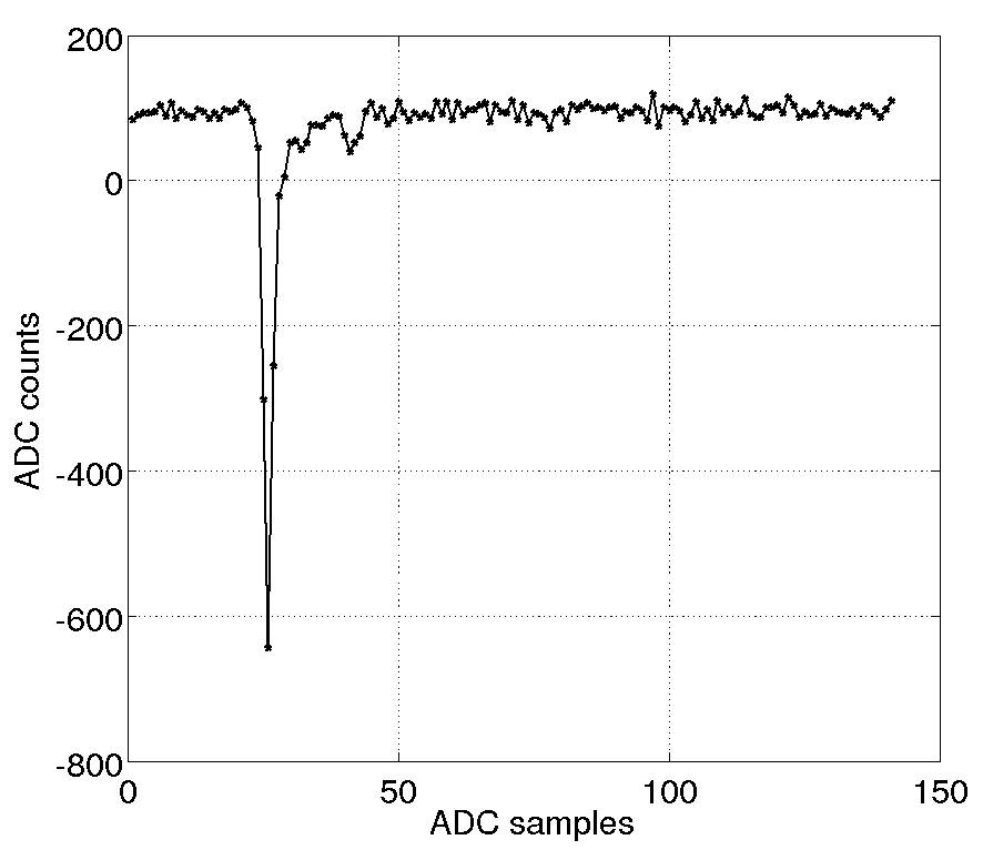
The signal from the beam loss detector (usually a photo-multiplier tube) is typically a unipolar pulse or train of pulses with negative polarity. Example of a loss signal is shown in the figure below.
Processing is split to 2 general principles:
Data from both modes can be used in parallel.
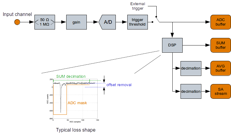
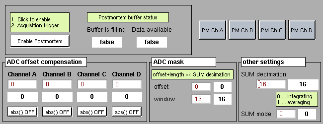
In the buffered mode, the raw sampled data is stored in a buffer upon a trigger event (auto-trigger or external). Digital signal processing includes DC offset removal, integration/averaging interval and ADC mask which is applied to raw ADC samples. Decimated data is stored in the SUM and AVG buffers and streamed to a continuous SA data stream according to figure below.
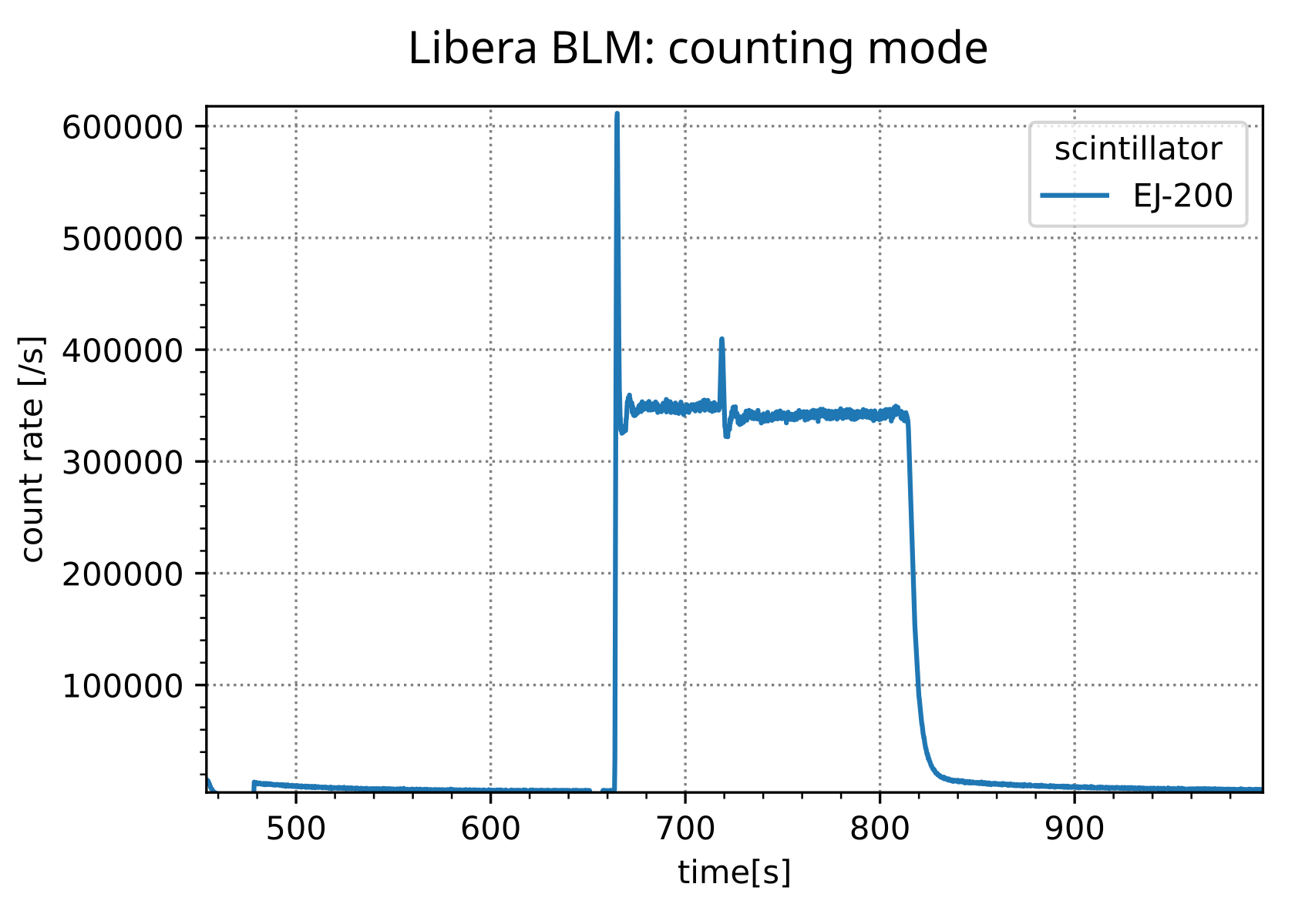
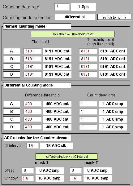
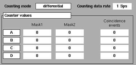
In the counting mode, the raw sampled data is continuously (8 ns) monitored to automatically detect individual loss events and count them based on adjustable absolute or relative thresholds logic. The output of this stream is “counts per period” (e.g. counts/s.)When the A/D converter is locked to a reference clock, it is possible to adjust up to two configurable detection windows that monitor only a selected part of the fill pattern. Outputs are 2 counter streams according to figure below.

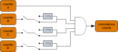
With up to 4 beam loss detectors connected to the same instrument, an algorithm can automatically detect if the loss was detected in all detectors within the same time window. This is called coincidence counting mode. Coincidence is counted for each of the 4 channels resulting in 4 coincidence counting data streams. Configuration logic (example for master channel A) is shown in figure below.
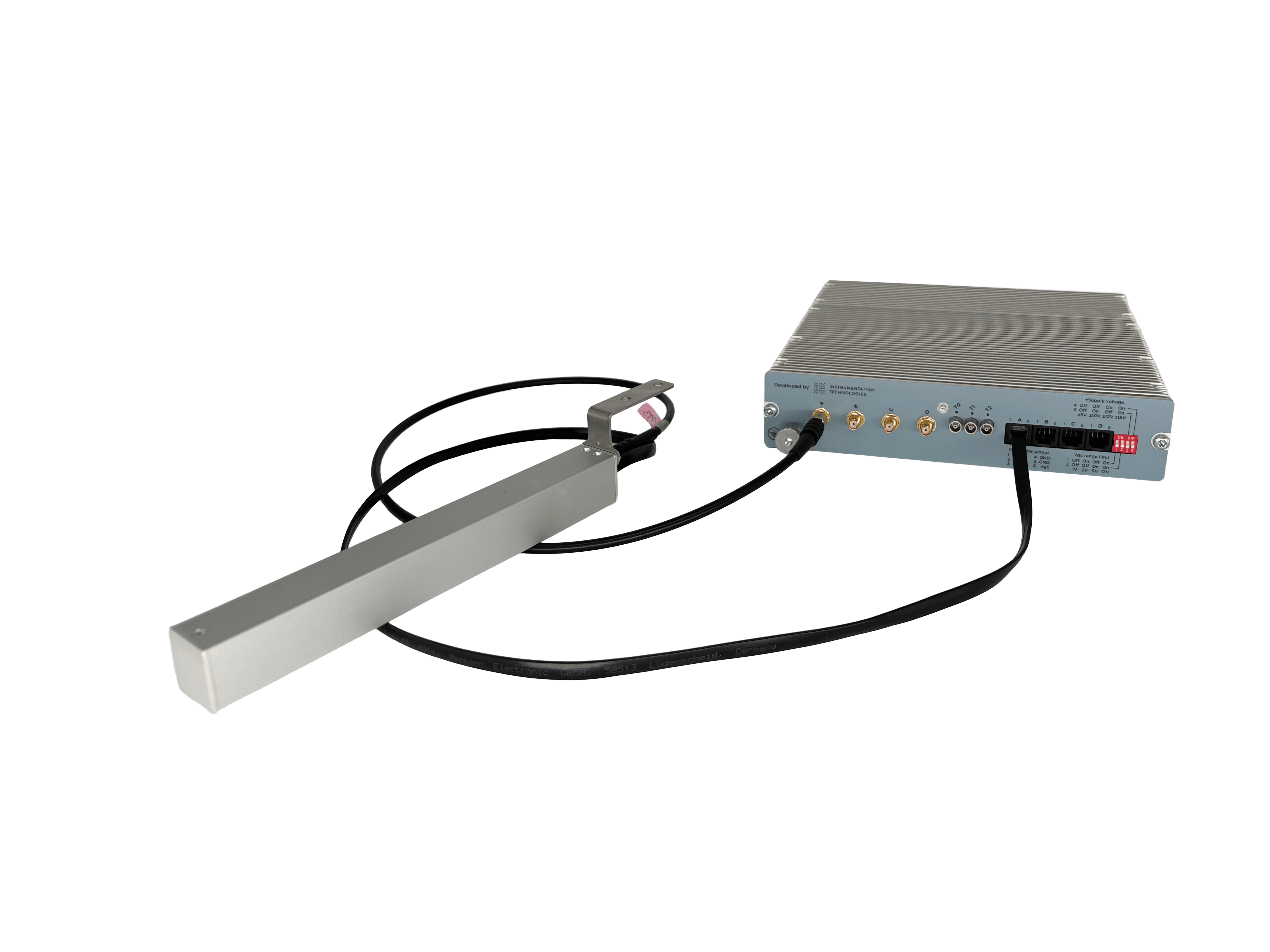
Libera BLM front and back panel:

Set-up example:
Libera BLM provides the power and gain control voltage to up to 4 beam loss detectors via standard flat cable (6 wires). High voltage is generated inside the photo-multiplier tube (PMT). Output signal from the PMT to the Libera BLM is provided through a standard 50 Ohm coaxial cable.
Beam loss detector must be exposed to the electromagnetic shower. The scintillator is located in the upper part of the detector, about 11 cm from top. Orientation of the detector with reference to the vacuum chamber shall be decided after tests. Typically, it is positioned vertically or horizontally and fitted to the vacuum chamber directly.
Libera BLM block diagram:
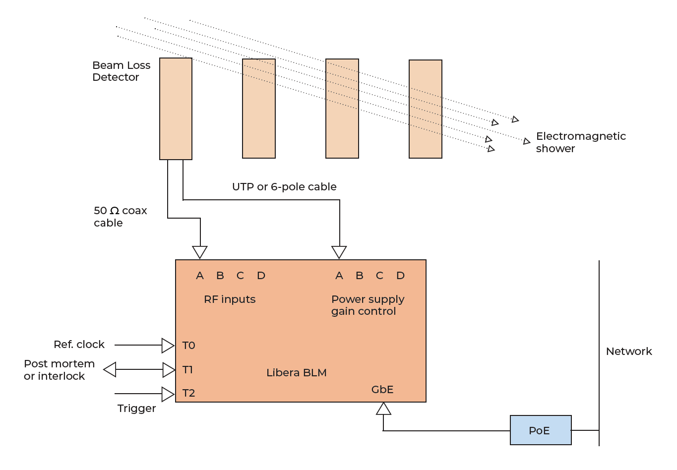
The Libera BLM is installed outside the tunnel. Cable lengths for the beam loss detectors can range up to 100 meters (tested).
The instrument runs on a Libera BASE software infrastructure. The infrastructure supports various plugins (interface servers) that are compatible with most common control system interfaces on users’ side:
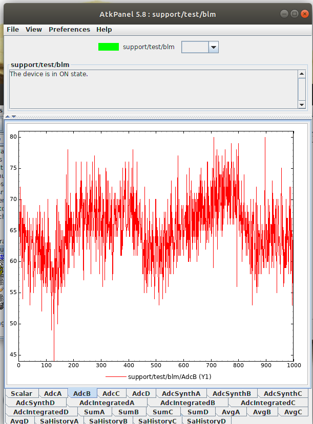
Graphical user interface for TANGO users is built by the AtkPanel tool automatically.
EPICS users have various options: from EDM, caQtDM to CSS.

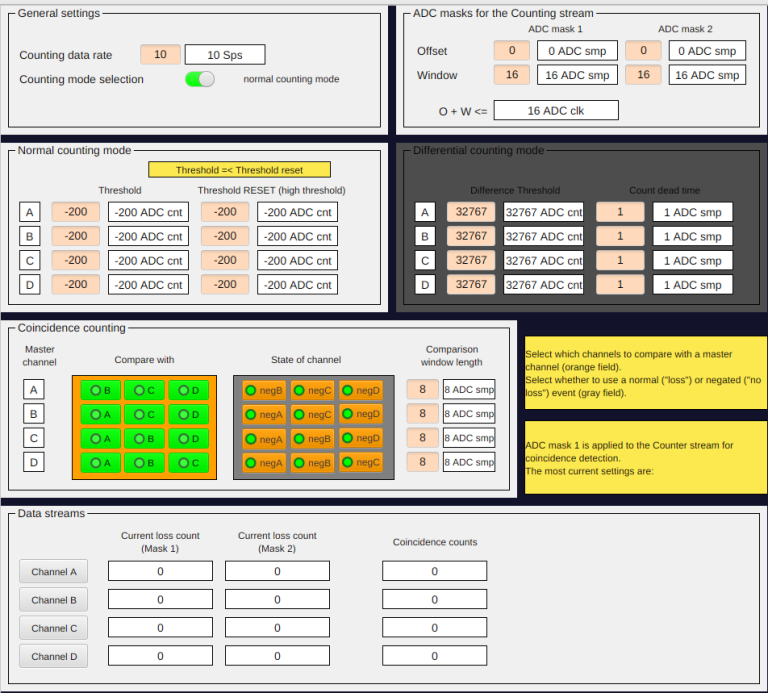

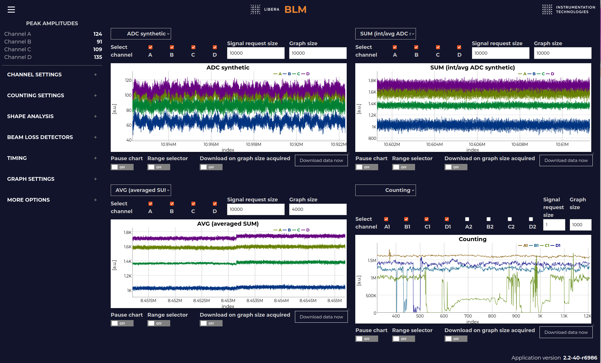
Another very intuitive and easy-to-start interface is the BLM Web GUI, which runs on the users web browser and allows users to access instrument parameter nodes and read out signals without having to understand Linux, ssh and command line interfaces or go through the whole procedure of installing EPICS or TANGO.
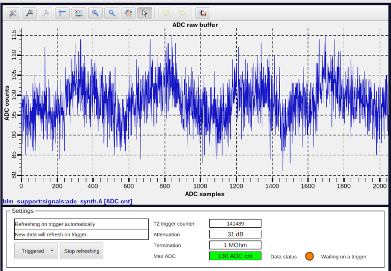
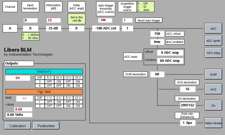
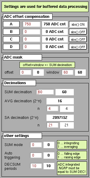
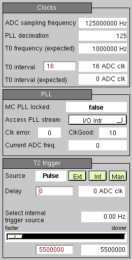
As an example, the gallery below shows the GUI panels built on the EDM technology.



| General product code | LBLM |
| Input channels | 4 |
| Input frequency range | ~35 MHz large signal bandwidth ~50 MHz small signal bandwidth |
| Matching impedance | 50 Ohm / 1 MOhm, software selectable |
| A/D conversion | 125 MHz, 14 bit |
| Cooling | Passive |
| Power supply | PoE |
| Timing signals | Electrical, 3 inputs |
| Maximum input signal | ± 5 V @ 50 Ω ± 1.25 V @ 1M Ω |
| Output channels | 4x power supply (up to ±15 V) 4x gain control (up to +12 V) |
| Dimensions | H: 1 U, W: 9.5" (rack mountable with a kit), D: 210 mm |
| Application | Description |
|---|---|
| Low loss detection | Detecting volumes as low as a single electron loss using high input impedance and high gain |
| Strong and fast loss detection | Detecting strong losses during injection (typically) |
| Automatic loss detection | Adjustable threshold for automatic buffer storage |
| Configurable processing parameters | ADC offset compensation, integration and averaging window lengths, loss detection windows and individual channel delays |
| Counting modes | Select between static and dynamic thresholds for loss counts. Apply a custom recovery time and threshold |
| Coincidence loss detection | Compare up to 4 channels for simultaneous loss events |
| Loss value calibration | Compensate the raw loss value with current gain settings (attenuation, photosensor, dynamic gain and photosensor static gain) |
| Postmortem data storage | Dedicated memory buffer is intended for storing the data just before a postmortem trigger event |
| Photosensor control | Provide power supply and adjust gain control voltage to up to 4 independent channels |
| Interlock detection and output | Monitor the accumulated loss value and trigger an output signal for the machine protection system |
Libera BLM is used at the following labs:
Can’t find your discipline or profession? Write to us and we’ll
do our best to work something out.
We adjust our services to your needs.